

Every action relative to depolarisation in a pacemaker works on a timer, and the programming of an implantable pulse generator effectively comes down to the setting of various timers.
These timers can complete one of two tasks; finish the cycle and completely timeout before restarting, or reset if a native P or R wave is sensed (ectopic or otherwise) and start the cycle from the beginning again.
Intervals denote the length of time between two events. These intervals are usually measured in milliseconds, as despite often being programmed in ppm, devices in fact “see” in ms. It is therefore necessary for practitioners to be able to flit between rate and interval quickly. Finding rate from interval, or vice versa requires a simple calculation:
INTERVAL to RATE

RATE to INTERVAL

The relationship between both elements being the longer the interval length, the slower the rate.
Common Timing Cycles in Single and Dual Chamber Pacing

Single-Chamber Timing
As discussed in previous sections of these pacing pages, single chamber devices either pace or sense in the atrium or ventricle, depending on the chamber the lead is placed in.
Timing cycles in single-chamber devices comprise three components;
- Lower Rate Limit
- Alert Period
- Refractory Period
- Absolute (Blanking Period)
- Relative

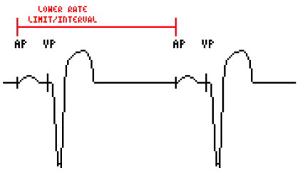
Lower Rate Limit (LRL)
This is the lowest rate at which the PPG will pace. If for instance, a device is programmed VVI at 70ppm, it will maintain this rate when the patient’s intrinsic rate is less than 70bpm. A sensed or paced event resets the timer on the LRL interval at the rate it is programmed.
Alert Period
Also known as the Blanking Period, this is the portion of the entire cycle that allows the device to sense and pace. On the above diagram, it is represented by the period after the terminus of the relative refractory period, and the start of the next absolute refractory period.
This timespan is not directly programmable by practitioners, but by adjusting refractory periods, it is possible to control the alert period.
Refractory Period
To simplify this period, liken it to the refractory period of the heart’s nodal cells. After the sinoatrial node has generated an impulse, it becomes unresponsive to further impulse until its “timer” has expired. Of course, it’s more complicated than that, but as a jumping-off point, that analogy works well.
The pacemaker refractory period can be further separated into two parts;
- Absolute refractory period
- Relative refractory period
During the absolute refractory period the pacemaker’s ability to “see” native signals is inhibited, so it will not detect any stimulus whatsoever.
Every timing interval starts with an absolute refractory period. It prevents unwanted sensing of other signals, including the pacemaker sensing itself.
Magnet Modes

AOO (atrium) and VOO (ventricle) modes are a single chamber device’s asynchronous operational setting. Induced using a magnet, these modes inhibit sensing, and pace at a programmed rate regardless of native stimulus as in the example diagram above.
VVI/ AAI Mode

VVI and AAI pacing are modes in which pulse generation is inhibited when intrinsic activity is sensed. In the diagram above (VVI), a native signal is sensed before the termination of the lower rate limit timer, so the clocks, including absolute and relative refractory periods, are reset completely.
If no chamber activity is sensed, then the chamber is paced at the lower rate limit.
Dual-Chamber Timing
Due to the complexity in dual-chamber pacing, compared with that of single-chamber, there are a number of extra timers involved in the process:
- Lower Rate Limit
- Upper Rate Limit
- AV and VA Intervals
- Refractory and Blanking Periods
- Post-Ventricular Atrial Blanking Period (PVAB)
- Post-Ventricular Atrial Refractory Period (PVARP)
Lower Rate Limit
Similar to single-chamber modes, in that this denotes the lowest rate at which the PPG will induce depolarisation in the absence of native events.
Upper Rate Limit
Also known as the Upper Sensor Rate, it is the maximum rate at which the ventricles can be paced in response to atrial events;
Consider a patient has their pacemaker set to 60ppm. This would be a perfect rate whilst resting, but during exercise the heart will need to beat faster to meet the increases oxygen demand. In this case, the leads in both chambers are programmed to pace at an upper limit. If the lead in the atrium begins to pace at an increased rate, then the lead in the ventricle, recognising this, will increase accordingly.
If, however, the atria were to enter an atrial tachyarrhythmia, the rates could reach up to 300bpm. The upper rate limit programmed in the ventricular lead (let’s say at 130ppm), stops the ventricles from being paced at a rate that matches that of the atrium, and ignores rates that suggest pathology.
AV Interval (AVI)

The AV interval is designed to mimic the P-R interval; the natural pause caused by the AV node during a normal cardiac cycle. The slowing of the signal allows for adequate filling of the ventricles in order to facilitate a healthy cardiac output.
The paced AV delay timer is programmable, and is initiated by the paced atrial impulse. It operates in;
- DDD
- DDDI
- DVI and
- DOO
Sensed AV delay begins operation after the detection of a native atrial impulse generation. In order for this to occur, it must be programmed to be of a roughly 25ms shorter value than that of paced AV delay.
By doing this, it gives the PPG time to sense the intrinsic event, as there is a slight time difference in the impulse generation and signal sensing.
VA Interval
This is longest period of time during a pacing cycle. Sometimes called the atrial escape interval, it represents the time taken to pace the atrium, in the absence of native activity, after a ventricular depolarisation.
It can be found with;
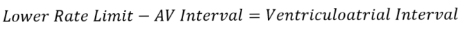
The AVI determines whether the ventricle will be paced, and the VA interval does the same for the atrium.
Refractory Periods
PVAB is initiated by ventricular activity, and like the absolute refractory period in single-chamber devices it ensures that the device’s atrial channel doesn’t sense or respond to signals generated.
PVARP is essentially a safeguard to prevent restarting of the AV delay timer. It begins after PVAB, with ventricular activity, and acts on the atrial channel of the device in order to avoid tachycardia caused by the pacemaker.
The timer ensures that the PPG will not respond to any atrial activity, and will not act upon the signals generated by the ventricular lead or by T waves, by inhibiting far-field sensing. It allows the device to record activity, however.
Normal settings are circa 250-275ms

